How to choose vibration testing equipment for product reliability and packaging tests
Choosing vibration testing equipment is a practical engineering decision. The system has to reproduce the required vibration profile while safely carrying the test item, fixture, and any table extension. In many labs, the main choice is between electrodynamic shakers for controlled sine, random, and shock profiles; mechanical vibration tables for simpler packaging evaluations; and hydraulic systems for high-force, lower-frequency structural work.
The right choice depends on the test standard, payload mass, frequency range, displacement, acceleration, mounting direction, controller capability, and reporting requirements. A system that looks strong on one catalog rating can still fail the job if it lacks low-frequency stroke, high-frequency table stiffness, or enough control channels for the fixture layout.
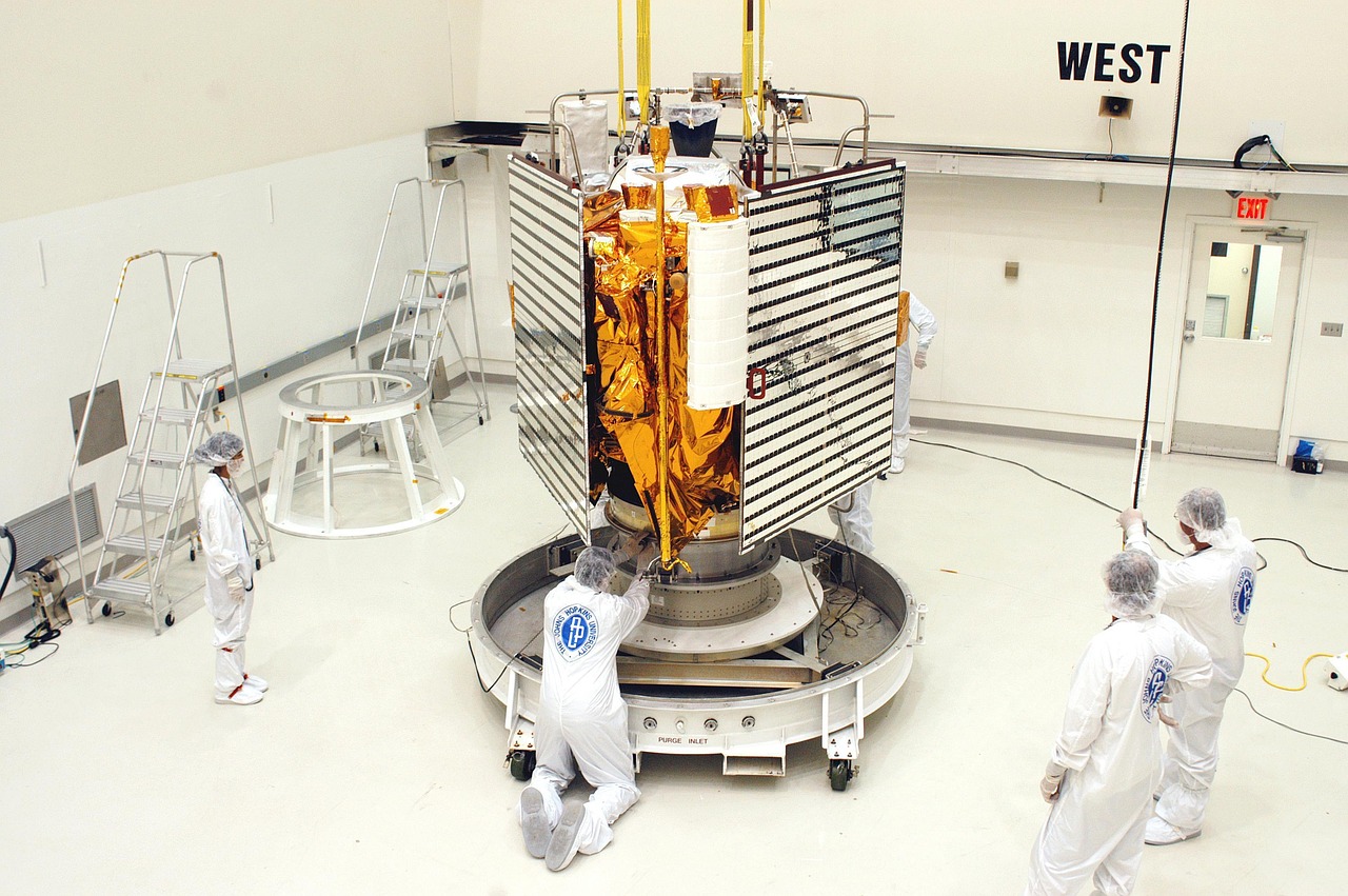
This guide is intended for engineers, buyers, and lab managers comparing vibration test systems for product qualification, transportation simulation, electronics testing, and packaging validation.
Start with the test purpose before comparing shaker size
Vibration testing is used for several purposes, and each one places different demands on the equipment. A product reliability test may need controlled random vibration to expose mechanical weakness in solder joints, connectors, brackets, sensors, displays, or fasteners. A packaging test may focus on whether a filled shipping container and its cushioning system can protect the contents during transportation. A development test may use resonance search, dwell, or sine sweep procedures to understand the product’s dynamic behavior before final qualification.
The first selection question is therefore not “How large is the shaker?” but “What environment must the system reproduce?” A test based on field transportation data, a customer specification, or a recognized standard will usually define the frequency range, acceleration level, duration, axes, mounting condition, and acceptance criteria. Without those inputs, equipment selection becomes guesswork.
Commonly referenced documents include IEC 60068-2-6 for sinusoidal vibration, IEC 60068-2-64 for broadband random vibration, ISO 16750-3 for mechanical loads on road-vehicle electrical and electronic equipment, and ASTM D999 for vibration tests of filled shipping containers. These standards do not all test the same thing. Some focus on unpackaged components; others apply to packages, vehicle-mounted electronics, or transportation effects. Selecting equipment before identifying the applicable standard can lead to a system that is oversized in one area and inadequate in another.
For more articles in this category, see the testing equipment section.
Main types of vibration testing equipment
Most vibration labs use one or more of the following equipment categories. The names are sometimes used loosely in sales literature, so it is better to compare them by motion control, frequency capability, payload range, and intended application.
Electrodynamic vibration shakers
Electrodynamic shakers are widely used for controlled product vibration testing. They use an electromagnetic drive system, a power amplifier, a vibration controller, and an armature or slip table to produce repeatable motion. Typical test modes include sine sweep, fixed-frequency sine dwell, random vibration, classical shock, transient events, and combined profiles such as sine-on-random when the controller supports them.
The main advantage is control precision across a broad frequency range. Electrodynamic systems are common in electronics, automotive components, aerospace subsystems, sensors, instruments, and small-to-medium mechanical assemblies. They are also used with head expanders or slip tables when the test item needs a larger mounting area or horizontal-axis excitation.
Mechanical vibration tables
Mechanical vibration tables are often used for simpler packaging and transportation simulations. They may provide repetitive motion suitable for evaluating filled containers, closures, cushioning, and package-product interaction. Their control precision is usually lower than that of a modern electrodynamic shaker with closed-loop digital control, but they can be appropriate when the required method is relatively simple and the acceptance criteria are visual inspection, package integrity, or product function after exposure.
Hydraulic vibration systems
Hydraulic systems are generally considered when the test item is heavy, the required force is high, or the vibration is concentrated at lower frequencies. They are less common for high-frequency electronics qualification, but they may be relevant for large structural assemblies, heavy components, and applications where displacement and force matter more than high-frequency bandwidth.
Multi-axis and combined-environment systems
Most conventional vibration tests excite one axis at a time. Some applications, however, require multi-axis excitation or vibration combined with temperature, humidity, or operational loading. Combined-environment testing adds complexity because fixtures, cables, sensors, chamber interfaces, and safety interlocks must all work together. It is usually better to define the combined test requirement early rather than adapt a basic shaker after purchase.
Specifications that actually determine whether the equipment can run the test
Shaker brochures often highlight one impressive number, such as maximum force or maximum acceleration. In practice, the usable test envelope is defined by several limits at the same time. A system must meet the required force, displacement, velocity, acceleration, frequency range, and payload capacity under the actual fixture and test-item configuration.
| Specification | Why it matters | Common selection mistake |
|---|---|---|
| Force rating | Determines how much mass can be accelerated at the required level. | Considering only the product mass and forgetting the fixture, armature, head expander, or slip table. |
| Displacement or stroke | Critical for low-frequency vibration where large movement may be required. | Choosing a system with enough acceleration at high frequency but insufficient stroke at low frequency. |
| Velocity | Can limit mid-frequency sine testing and some transient profiles. | Checking force and acceleration but ignoring velocity limits. |
| Frequency range | Defines the practical operating band for the test profile. | Assuming the advertised maximum frequency is usable with every payload and fixture. |
| Payload capacity | Sets the safe mechanical load on the armature or table. | Mounting a heavy fixture that consumes the payload margin before the product is installed. |
| Controller channels | Support control, monitoring, notching, averaging, and safety shutdown. | Buying a controller with too few inputs for complex fixtures or multiple response points. |
The basic relationship behind shaker sizing is straightforward: required force rises with moving mass and acceleration. The moving mass includes more than the product. It also includes fixtures, bolts, adapters, head expanders, slip tables, and the moving part of the shaker system. For random vibration, engineers also need to evaluate the root-mean-square acceleration, the power spectral density profile, and the system’s random force capability instead of relying only on a peak sine-force value.
Low-frequency requirements deserve special attention. A vibration profile that looks moderate in acceleration can demand large displacement at low frequency. Conversely, a high-frequency test may be limited by fixture stiffness, control stability, accelerometer placement, or cross-axis motion rather than by nominal force.
Match the equipment to the relevant standards and test documents
Standards are useful because they define repeatable methods, but they should not be treated as interchangeable. IEC 60068-2-6 is associated with sinusoidal vibration and is often used to determine whether a specimen can withstand specified sine severities. IEC 60068-2-64 addresses broadband random vibration for specimens exposed to stochastic vibration environments such as transportation or operation in vehicles. ASTM D999 covers vibration tests of filled shipping containers and emphasizes the performance of the container, interior packing, closure, and contents when exposed to transportation vibration. ISO 16750-3 applies to mechanical loads for road-vehicle electrical and electronic systems and components.
These differences matter when choosing equipment. A package vibration table suitable for a shipping-container evaluation may not provide the closed-loop random control required for an electronics qualification test. A high-frequency electrodynamic shaker suitable for a small circuit module may not have the table size or load capacity needed for a palletized shipping configuration. A vehicle component test may require specific mounting orientation, operational monitoring, or axis sequencing that should be considered before equipment is ordered.
Standards also affect documentation. A compliant report may need test levels, tolerances, axis orientation, mounting details, accelerometer locations, calibration status, test duration, interruptions, functional checks, anomalies, and photographs of the setup. If the controller software cannot export the required plots and logs, the test may be difficult to defend even if the hardware completed the profile.
Fixtures, mounting, and sensors can change the test result
Vibration testing equipment is only as reliable as the complete test setup. The fixture transfers motion from the shaker to the test item, so fixture stiffness, mass, resonance behavior, bolt pattern, and surface flatness all influence the result. A poorly designed fixture can amplify vibration at some frequencies, attenuate it at others, or introduce cross-axis motion that makes the test less representative. See also: buying guides.
For component testing, the fixture should normally represent the product’s real mounting condition as closely as practical. If a bracket, rail, or mounting plate is part of the in-service configuration, it may need to be included or accurately simulated. For packaging tests, the container orientation, closures, cushioning, fill condition, and product placement should match the intended distribution condition.
Accelerometer placement is another major factor. A control accelerometer is commonly mounted near the fixture-test item interface, while response accelerometers may be placed on critical product locations. Multi-point control, averaging, or notching may be needed when the test item is delicate, the fixture is large, or different mounting points respond differently. Notching should be used carefully: it can protect the test article from unrealistic overtest, but it can also reduce input severity if there is no justified control strategy.
Cabling is often overlooked. Loose cables can add unwanted dynamic loads, strike the fixture, or affect small test items. Cable loops should be secured without restricting intended motion. Sensor mass should also be considered when testing lightweight parts, because even small accelerometers can influence local response on thin panels or miniature assemblies.
A practical selection checklist for buyers and lab managers
Before requesting quotations or approving a purchase, build a test matrix rather than a generic specification sheet. The matrix should list each expected test profile and the most demanding combination of mass, axis, frequency range, acceleration, displacement, velocity, duration, and table configuration. The most severe test may not be the one with the highest acceleration. It could be the one with the largest fixture, the lowest frequency, the longest duration, or the tightest tolerance.
- Define the application. Identify whether the system will mainly test electronics, instruments, automotive parts, packaging, heavy structures, or mixed workloads.
- List the standards and customer specifications. Include the exact test methods, axes, durations, and acceptance criteria where available.
- Calculate total moving mass. Include the product, fixture, adapters, head expander, slip table, and any representative accessories.
- Check force, stroke, velocity, and acceleration together. Do not select equipment from one headline rating.
- Confirm table size and mounting pattern. The product must fit without unsafe overhang or unrealistic mounting changes.
- Review controller capability. Look for the required modes, channel count, safety limits, notching options, data export, and report generation.
- Plan calibration and maintenance. Accelerometers, controllers, amplifiers, cooling systems, bearings, and slip tables all need periodic attention.
- Consider noise, cooling, and facility requirements. Larger systems may require compressed air, cooling water, reinforced floors, electrical upgrades, acoustic controls, or safety guarding.
For labs that handle varied projects, it is often wise to reserve margin in both force and table capacity. However, margin should be targeted. Oversizing can increase cost, floor loading, energy use, fixture expense, and operational complexity. Undersizing can force test compromises, outsourcing, or premature equipment replacement.
Common limitations and risk points
One common misconception is that a shaker reproduces the entire real-world vibration environment. In fact, a base-driven test mainly controls vibration at the mounting interface. It may not reproduce all acoustic loading, multi-axis input, road impacts, handling shocks, or product-specific boundary conditions. That does not make laboratory testing invalid; it means the test plan should state what the test is intended to prove and what it does not cover.
Another risk is confusing development testing with qualification testing. During development, engineers may intentionally search for resonances, explore failure modes, or run step-stress profiles. Qualification testing is usually more controlled and must follow defined procedures. The same vibration testing equipment may support both, but the setup, documentation, and acceptance criteria should be different.
Fixture resonance is also a frequent source of misleading results. If the fixture has a strong resonance inside the test band, the product may see higher or lower input than intended. A fixture evaluation, low-level pretest, or resonance survey can help identify these issues before the full-level run. For high-value or fragile items, gradual level increases and protective abort limits are prudent.
Finally, packaging tests and product tests should not be mixed without care. A package test can show how a container and cushioning system perform during distribution-like vibration. It does not automatically prove that the unpackaged product is robust in operation. Likewise, a component vibration qualification does not automatically prove that the shipping package protects it.
Frequently asked questions
What is the difference between sine and random vibration testing?
Sine vibration uses a controlled single-frequency input that can sweep through a range or dwell at a specific frequency. It is useful for resonance search, fatigue at known frequencies, and defined sinusoidal environments. Random vibration uses energy distributed over a frequency band and is often closer to transportation or operational vibration where many frequencies occur at the same time.
Is an electrodynamic shaker always better than a mechanical vibration table?
No. An electrodynamic shaker is usually better for controlled sine, random, shock, and qualification profiles, especially when detailed measurement and reporting are required. A mechanical vibration table may still be suitable for simpler packaging evaluations or routine transport-simulation checks when the applicable method and acceptance criteria support that approach.
How much capacity margin should a vibration test system have?
There is no universal margin because the answer depends on the test profile, fixture mass, duty cycle, and risk tolerance. In general, buyers should avoid selecting a system that only meets the calculated requirement under ideal conditions. A practical margin helps account for fixture changes, payload variation, controller limits, and future tests, but the margin should be evaluated across force, stroke, velocity, acceleration, and payload—not force alone.
Why does fixture design matter so much?
The fixture is the mechanical path between the shaker and the test item. If it is too flexible, too heavy, or poorly mounted, it can distort the input, introduce unwanted resonances, or create cross-axis motion. Good fixture design improves repeatability, protects the equipment, and makes the test result easier to interpret.
Can one vibration testing system cover product qualification and packaging tests?
Sometimes, but not always. A flexible electrodynamic system with suitable tables, fixtures, and controller modes may cover many component and small-package tests. Large shipping containers, palletized loads, or method-specific package tests may require different table geometry, payload capacity, or motion characteristics. The safest approach is to compare the complete test matrix against the full equipment envelope.
Conclusion
Effective vibration testing equipment selection begins with the required test environment, not the most impressive catalog rating. The equipment must match the applicable standard, product mass, fixture design, frequency range, acceleration, displacement, velocity, table configuration, controller functions, and reporting needs. Electrodynamic shakers are the most versatile choice for controlled product qualification, while mechanical tables and hydraulic systems remain useful for specific packaging, transport, and heavy-load applications.
The most useful preparation is a clear test matrix that includes standards, axes, payloads, fixtures, profiles, tolerances, and documentation requirements. With that information in hand, engineers can compare systems on usable capability instead of headline specifications and reduce the risk of buying equipment that cannot run the tests that matter.